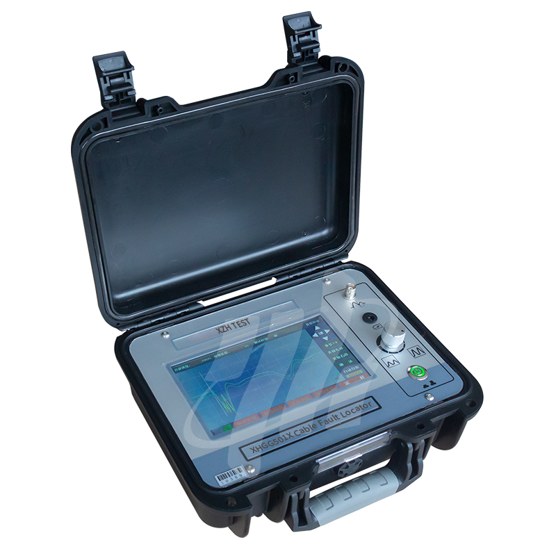
XHGG501XMáy định vị lỗi cáp
Máy định vị lỗi cáp tiên tiến với công nghệ Phản xạ miền thời gian (TDR) để kiểm tra khoảng cách lỗi chính xác với độ phân giải tối thiểu 0.1m hàng đầu trong ngành.
Máy kiểm tra lỗi cáp này thực hiện lấy mẫu ba pha ABC riêng biệt và dạng sóng lấy mẫu được hiển thị trên màn hình cùng một lúc, để có thể so sánh dạng sóng của cáp ba pha. Thiết bị có các chức năng tốc độ lấy mẫu xung đầu ra thích ứng và phân tích dạng sóng tự động, và ứng dụng rất đơn giản.
Đặc điểm sản phẩm
| Chiều dài kiểm tra tối đa | không dưới 50km |
| Tốc độ lấy mẫu | 10MHz, 20MHz, 50MHz, 100MHz, 200MHz |
| Độ rộng xung | 1us, 0.75us, 0.5us, 0.2us, 0.1us |
| Biên độ xung | 400V |
- Công nghệ Phản xạ miền thời gian (TDR)
- Định vị lỗi cáp chính xác
 Khả năng kiểm tra khoảng cách
- Độ phân giải tối thiểu 0.1m
- Chức năng chẩn đoán thông minh
Nguyên tắc hoạt động
Máy kiểm tra lỗi cáp áp dụng nguyên tắc kiểm tra phương pháp sóng di chuyển:
1. Phương pháp sóng di chuyển: Khi sóng vô tuyến được truyền trong đường truyền, nếu đường truyền không đồng nhất, tức là trở kháng đặc tính của một điểm trong đường truyền thay đổi, khi sóng vô tuyến được truyền đến điểm đó, ngoài việc tiếp tục truyền đến tải, nó cũng sẽ tạo ra truyền ngược và quay trở lại đầu kiểm tra, chúng ta gọi truyền ngược của sóng là sóng phản xạ, hiện tượng sóng tạo ra truyền ngược được gọi là hiện tượng phản xạ của sóng. Cái gọi là sóng di chuyển đề cập đến tên gọi chung của sóng tới và sóng phản xạ.
2, khi sóng vô tuyến được truyền trong đường truyền, cực tính của tiếng vọng tại điểm ngắn mạch ngược với cực tính của xung phát ra và cực tính của tiếng vọng tại điểm đứt (bao gồm cả đầu cuối cáp) giống với cực tính của xung phát ra. Sử dụng phương pháp xung, thiết bị có thể dễ dàng xác định khoảng cách giữa điểm lỗi và đầu kiểm tra theo cực tính của tiếng vọng.
3. Máy kiểm tra lỗi cáp áp dụng tín hiệu xung điện áp thấp cho cáp đang thử nghiệm và tín hiệu xung tạo ra tín hiệu phản xạ thông qua điểm lỗi của cáp. Máy kiểm tra lỗi cáp xử lý tín hiệu phản xạ và trình bày sơ đồ dạng sóng. Khoảng cách lỗi thô của cáp đang thử nghiệm được xác định bằng cách phân tích dạng sóng phản xạ.
Phương pháp nối dây như sau: Sử dụng một đường Q duy nhất để kết nối "giao diện lấy mẫu" của máy kiểm tra lỗi cáp với đường pha bị lỗi và lớp che chắn cáp. Việc nối dây xung điện áp thấp được hiển thị trong hình dưới đây.
Lưu ý: Trong quá trình kiểm tra, phải xác nhận rằng không có điện nào được lưu trữ trong thân cáp.
Bước 1: Kẹp đường tín hiệu vào pha A cần kiểm tra. Việc lựa chọn pha kiểm tra của giao diện tương ứng cũng được đặt thành pha A. Sau đó nhấp vào nút lấy mẫu/giữ trên giao diện để vào trạng thái lấy mẫu. Quan sát dạng sóng lấy mẫu. Nếu bạn nghĩ rằng dạng sóng lấy mẫu tốt, hãy nhấp vào nút lấy mẫu/giữ để vào trạng thái giữ để phân tích dạng sóng. Tham khảo "Ví dụ về dạng sóng"-Phân tích dạng sóng.
Bước 2: Kẹp đường tín hiệu vào pha B cần kiểm tra. Lặp lại bước đầu tiên của quy trình kiểm tra.
Bước 3: Kẹp đường tín hiệu vào pha C cần kiểm tra. Lặp lại bước đầu tiên của quy trình kiểm tra.
Sau khi hoàn thành ba bước kiểm tra trên, giao diện sẽ hiển thị dạng sóng kiểm tra xung của cáp ba pha cùng một lúc.


Đánh giá chung
Hình chụp xếp hạng
Sau đây là phân phối của tất cả các xếp hạngTất cả các đánh giá